|
SPE 2K-FA failure report at VA2EW |

|

|
|
Written by Jilles VA2EW
|
 On 20 th May 2019 a few minutes after having switched it on and without having transmitting while the
amplifier was in RX mode on 15m I heard and see an explosion and a spark into the amplifier. The 25A wall
panel breaker switched off. That means a minimum of 60 amps short. On 20 th May 2019 a few minutes after having switched it on and without having transmitting while the
amplifier was in RX mode on 15m I heard and see an explosion and a spark into the amplifier. The 25A wall
panel breaker switched off. That means a minimum of 60 amps short.
I put the amp on a bench, none of the two fuses (high power for 48V and low power for other voltages) was
blown!
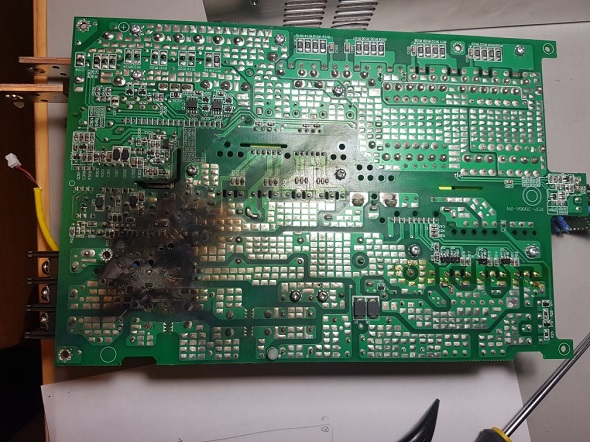
I removed the two external black panels (needs a hexagonal key) to have a view on the whole inside of the amps. No visible damage.
I then plugged again the amp to eventually locate the problem. When I switched it on, I again got a brief “blam” and spark and was then able to locate it inside the 48V power supply. This time the breaker did not switch off and still no fuse blew. The power was still on, the back-switch light was on as if nothing happened. It was not possible to start the amplifier pushing the ON key.
I then unplugged it and removed the two side screens protecting the amplifier modules (4 screw each) followed by the power line input small screen ( attention the flat head side screws, one on each side are 2,5mm when all other screws of the chassis are 3mm), removing the back small black panel supporting the fuses and all the stuff would have been a good idea for an easy access to the remaining. Then I removed the low voltages low power supply board including its connectors and was then able to unscrew the 240V connection to the 48V power supply module. I then had to remove all the stuff attached to the plus and minus
48V big output plates. Now there are just 4X4mm screws to remove from underneath the 48V module. Access
to these screws is from the amplifier modules place. Until then no trace of damage.
I then opened the top panel of the 48V module, and it was not that obvious to see that a component TNY-280P
was blown and actually cut into two parts the whole top of plastic case was ejected apart. This component is
providing a 12V standby output voltage from the internal about 400V of the module. This was explaining why
the amplifier was not any longer able to start. This 12V is needed to start the starting sequence of the
amplifier. But this small component blow was not explaining the big explosion and the 25A wall panel breaker
breaking.
After that I had to remove the whole 48V module PCB from its chassis and then I had my explanation: There was on the not visible side of the PCB a two inches diameter burn trace located close to the 240V input. BTW the 1.5-ohm/1W resistor R80 bringing current to the TNY-280P was blown too. After cleaning the smoke
traces, I could see that some small pieces of copper where
vaporated on the PCB in an unexplainable way:
there was no reason for a short due to a component between those tracks.
So we had a big short between the input Ground track and the input 240V “European neutral track” . That led me to two conclusions:
-As it is a European made amplifier in a country (Italy) where the standard home voltage is 220V, they are used to have a live 240V and a neutral 0V. So they only put one fuse on the live line. But here in North America we have 240V split in two lives 120V opposed phase. So never that amplifier would have been cleared by import authorities without two fuses, one on each phase, means one on each active wire. That’s the reason why none
fuse was blown, the short was between the ground and the “European neutral” which in NA is the 120V second phase. If a fuse were on that line, none of such explosion had happened.
-the second conclusion is that it is most possible that something conductive like a small piece of metal for some reasons put the two tracks into contact and then the short. It is obvious that this piece had been evaporated by the high current. So, the explanation of the short will never be found. There is still a provision as the blown up of the TNY-280P is not explained but a possible scenario is that while the TNY-280p was in short after its burn out, the 1.5 ohms/1W R80 which is a surface mound resistor located one inch from the exact location of the short exploded and sent a part of its inside highly conductive stuff just in between the ground and the “European neutral” creating the big short which switched the 25A wall panel breaker off.
So far, I was not aware that this 48V module was a standard industrial module. Looks like the label was removed and it is only by observing the PCB marking that I discovered that it was a Mean Well RSP-3000-48 made in Taiwan well distributed available everywhere in the world. I was happy to see that it will be easy to be replaced. But I had to do my research the Digikey price with taxes being about 830$ CAD. Finally, I got a used one from China via e-bay for 395$ CAD including every cost.
I could have tried to repair the original one but I was not able to find any Schematics as well as I was not 100%
sure that the origin of the failure was not caused by a bad command sequence from the amplifier (according to the documentation there is at least one sequence of signals on the RSP-3000 input command connectors that can blow some components inside and according to the 2K-FA schematics that I could find on the internet there is a possibility that a failure of a SCE-PE000075 A board component does the job. That way if in the
future I have the same problem again but with this new 48V module I will be sure that the problem is coming from the amplifier. Another point is that missing the schematics, by having in hand a second not burned RSP-3000, I could see by comparison what was eventually missing on the blown one.
By the way SPE Italy looks so proud of its amplifier and so persuaded that nobody can do better that even 8 years after the conception they are still not releasing schematics. It is by miracle that I could find a 2011 version of them which of course it not exactly corresponding to my amplifier but enough to help reverse engineering.
The same with Mean Well, I was not able to find schematics of the RSP-3000, I only found the RSP-1000 one which helped a bit as some pieces are the same. In the case of Mean Well I can understand their hesitation to release schematics: There are lethal over 400V voltages as well as very high instant catch on fire currents inside and they won’t encourage people to open it and try to repair it without strong knowledge in power
electronics.
Do not think that power supply in hand you just have to put it back in place and go. SPE had made a modification inside the RSP-3000. Maybe it is the reason why the original label has been removed.
So I first tested on bench the new power supply then put it in the amp, tested the amp without connecting the power supply connectors to the amplifier (providing external +12V wake up voltage) and then connected both.
I was first concerned by a strange problem: the power supply was refusing to switch in ready state (led staying red) when going in OPERATE mode. After investigations and several hours of work and retro-engineering I finally discovered the thing: Guess what?On the PCB of the power supply there are two 3 pins male connectors each one being connected to one of the two internal fan female connectors with standard black, red and white wires.
As I knew in order to control fans from the amp SPE have added a small interface board into the power
supply (board # SCE-PE000075 B)). To do that they have removed the two female fan connectors from the males on the PCB and plugged at their place the interface board into one of those male connectors while the other has a strap between ground and control signal. The fan female connectors are then plugged on two male connectors placed on the interface board. So they can control the fans with a two wire cable coming from the amp.
This interface board is necessary because the RSP-3000 fans are permanently running as soon as the module is connected to 240V even if no power is demanded. So to make the amplifier silent in RX mode one have to prevent the fan to run except when in OPERATE mode. It is the function of this module. The only default according to me is that when a long transmission at full power is finishing it would be a good thing to keep the fans running until the RSP-3000 has totally cooled. This module is not respecting that, it just cut the fans as soon as the operate mode is stopped. So it may be a good thing to let the amplifier in OPERATE mode (and of course switched on) a few minutes after
transmitting a long time even if you want to shut down the station quickly (at the end of a contest for example).
Now the thing which cost me several hours of work: Those #$%%## SPE engineers have designed the two male fan connectors on their fan interface board so that the red and black wires of the fan
connectors have to be swapped !!! You literally have to remove the pins from the female connectors and swap them !!! Then the modified female fan connectors are not any more compatibles with the initial connectors on the PCB. It is not a version evolution because I found the same thing on the former (blown) power supply.
I did not see that quickly because of course the wires are into a black heat shrinkable sheath. And how imagine such a stupidity or laziness into this board conception. I believe that the designer made the mistake of reversing the two pins but preferred swap the fan connector pins in the production process rather than modifying his PCB maybe because they discovered the error after having ordered and received a batch of 100+ boards from the subcontractor…
After 50 days the 2K-FA is back on service still under observation… The global cost of repairing, except my time was around 500 $ CAD (Cost of Power supply plus some stuff from Digikey to make my tests). That is not even the cost to send it to the North America Maintenance service in south of USA.
73, Gilles VA2EW |
